Plane: Aeroworks 104″ Yak-54 ARF QB™
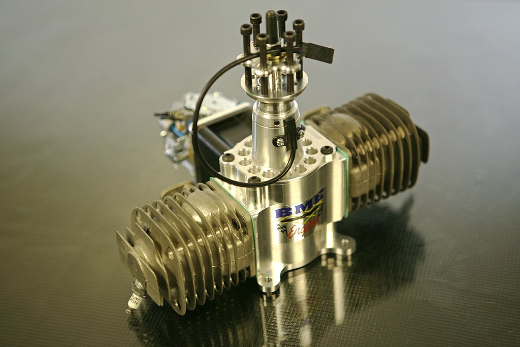
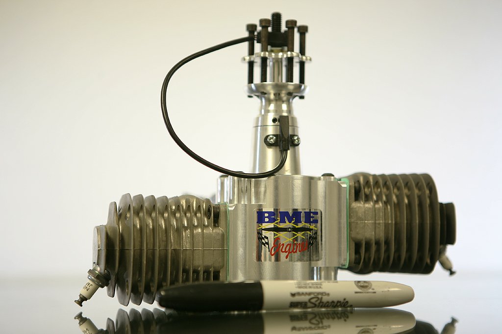
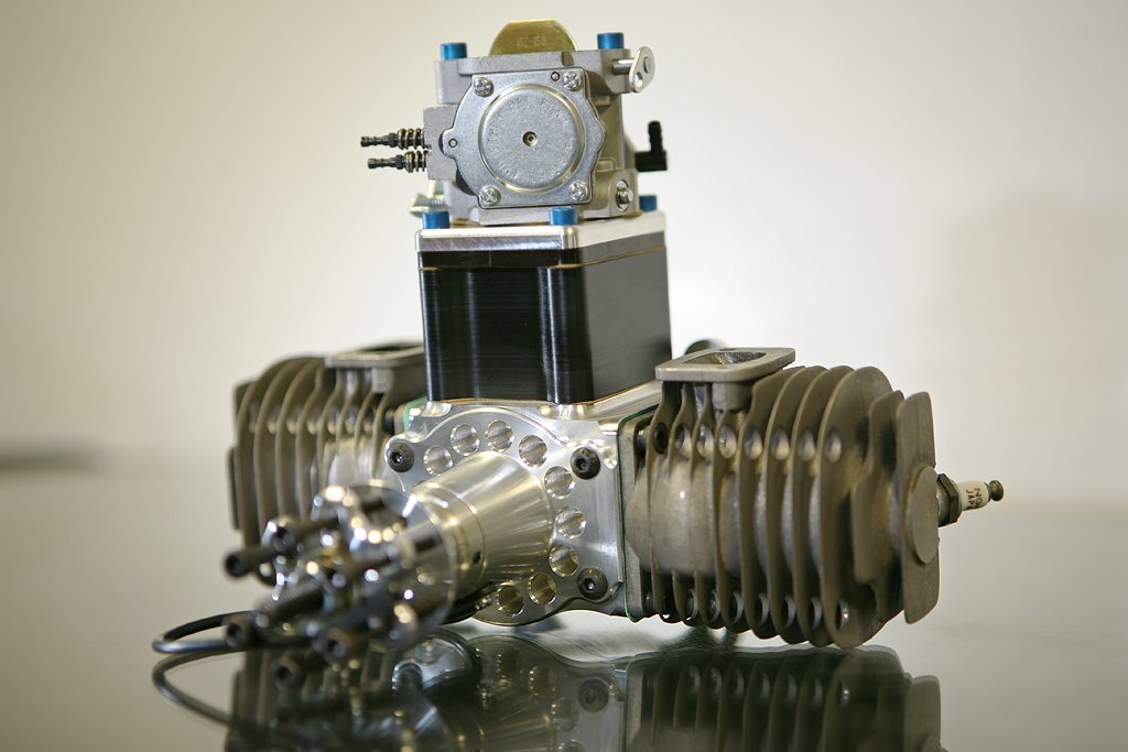
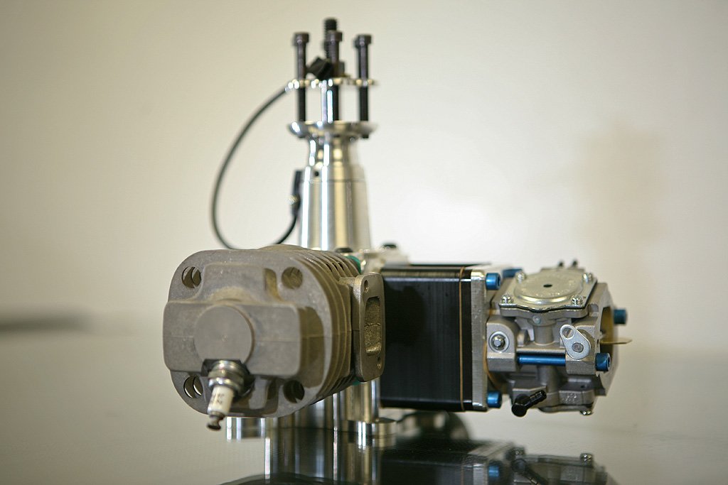
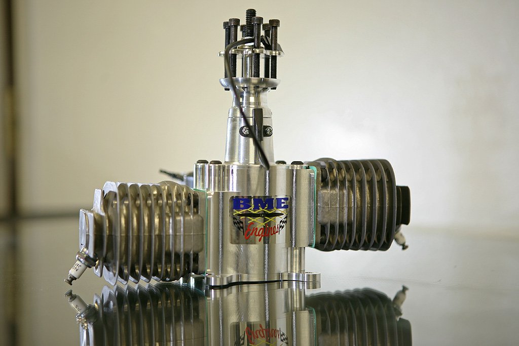
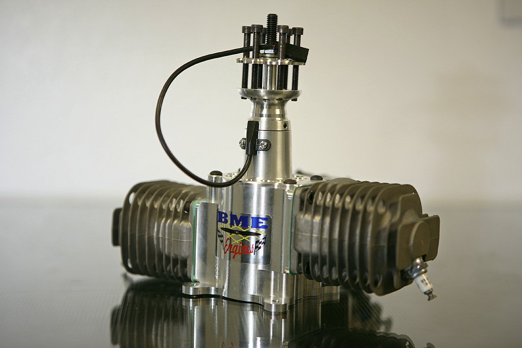
Engine: BME 115
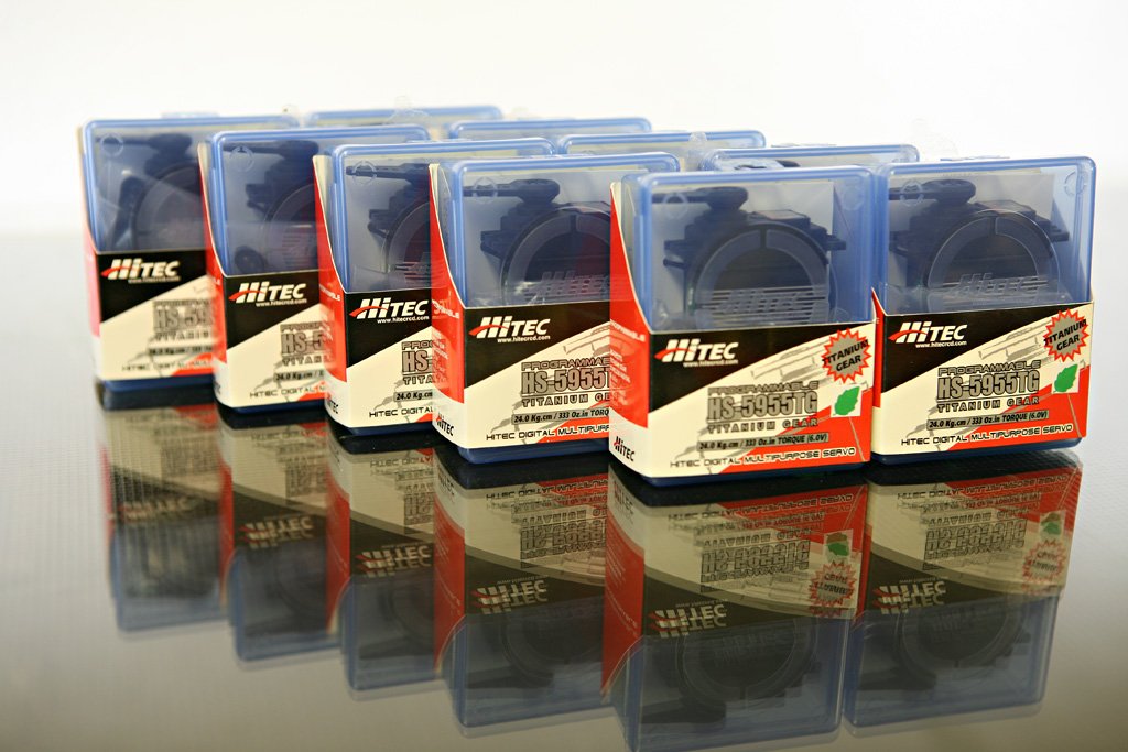
Servos: Hitec 5955s
Pros: Quick easy assembly, one of my all time favorite planes to fly.
Cons: My decision to try a BME 115
You can see in the Aeroworks parts slideshow (click here to watch the parts slideshow) that the shipping box now includes a plywood layer. When you unbox the thing you also see a lot of custom and well thought out packaging. These things are packed really well.
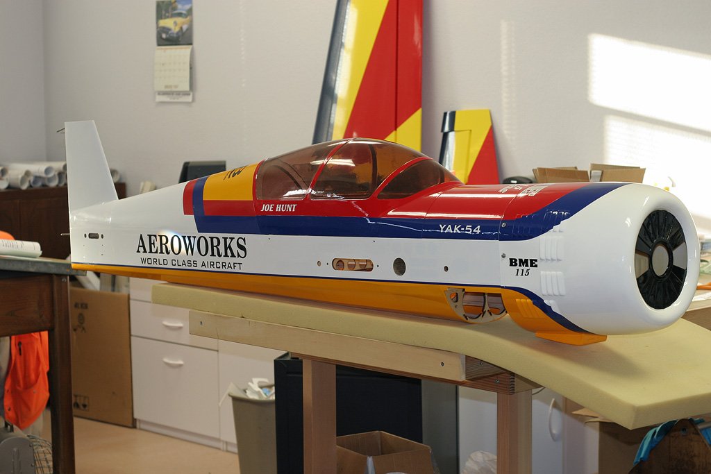
As with all the Aeroworks QBs… the plane seems RTF out of the box:
The fuse doesn’t feel exceptionally light, but the wings sure do! The leading edge and wing thickness makes me think it will really float/drag/fly stable. Also, huge ailerons, tons of throw and pre-glued in hinges. The hinges swing freely, as well:
The elevators also have pre-installed hinges (glued in), as you know… and with plenty of throw like all the Aeroworks QB™ planes:
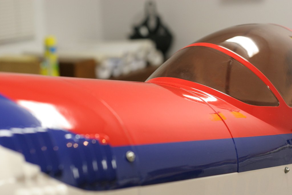
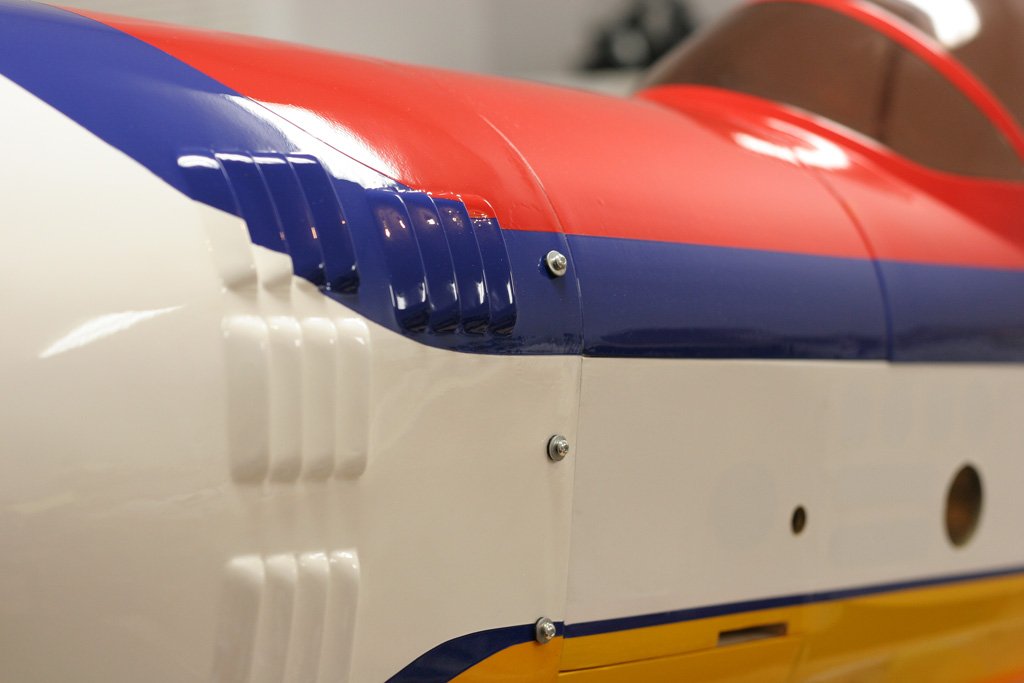
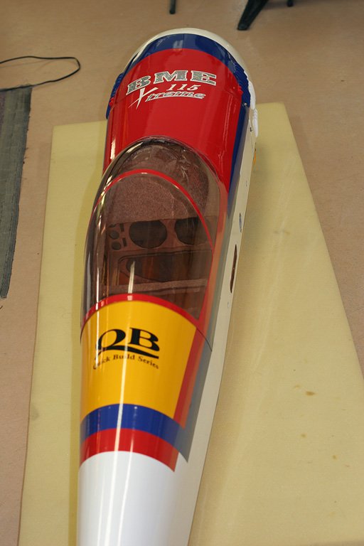
Here’s some shots of the canopy and side of the cowl… look at all that pre-done work… I’m spoiled on these now, if I got an ARF without the canopy pre-done I think it would just sit in the corner and never get assembled. The fit and finish on these modern day ARFs is rival’n the best builders. And, the Aeroworks ARF QBs have the best fit and finish I’ve seen:
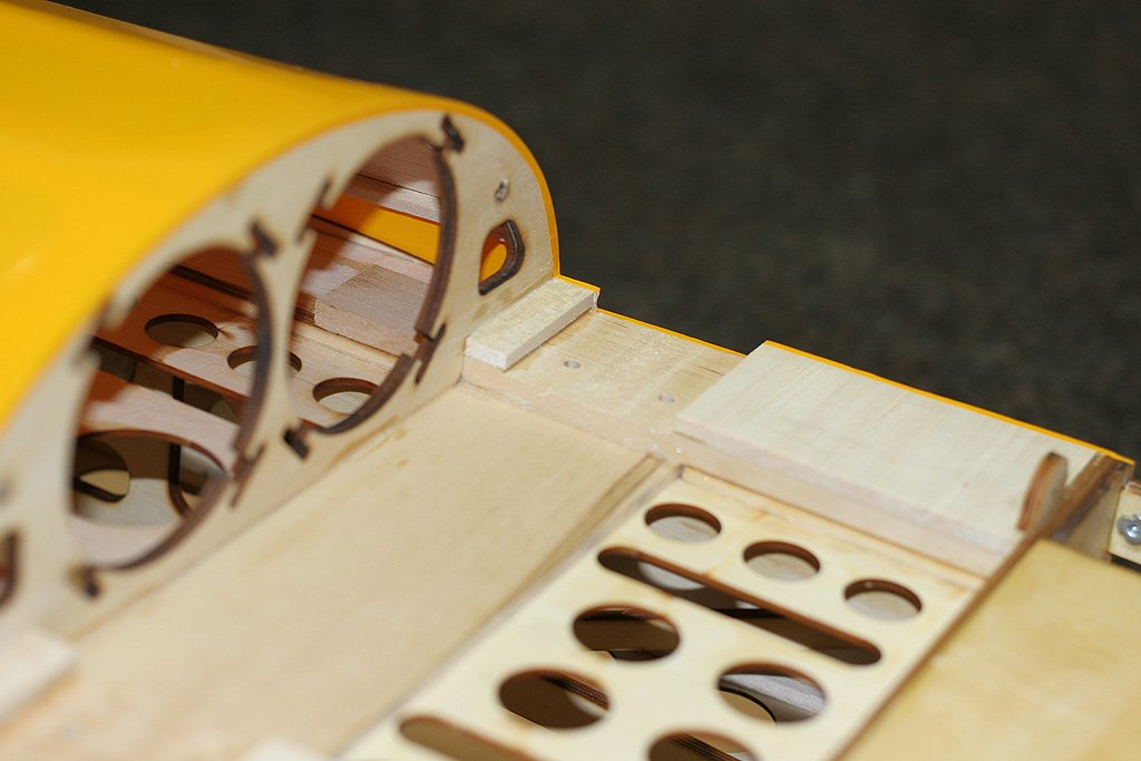
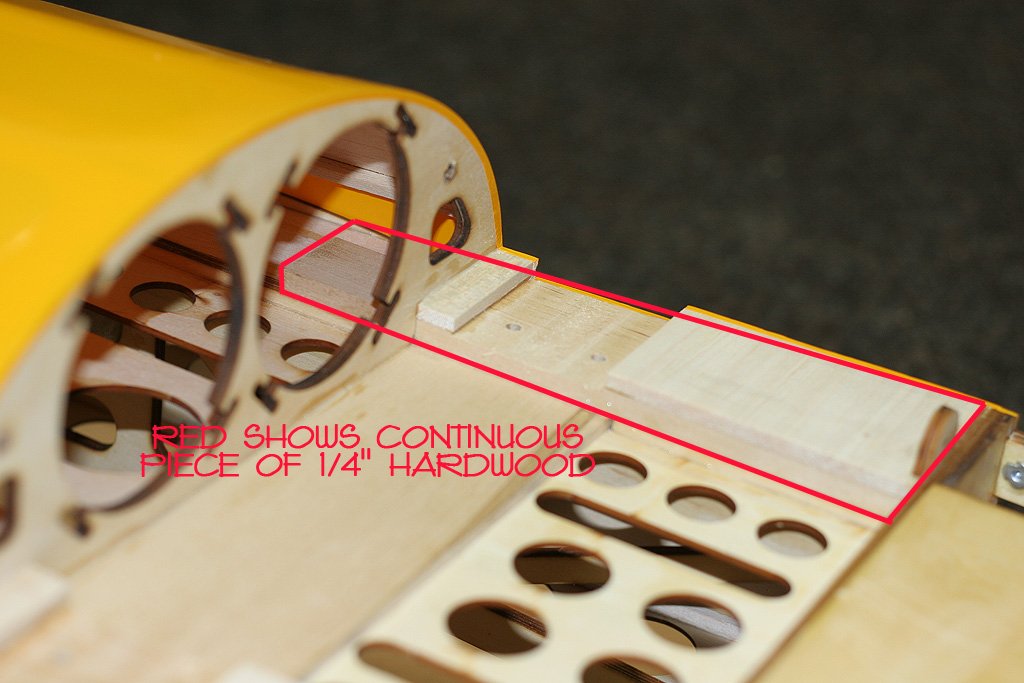
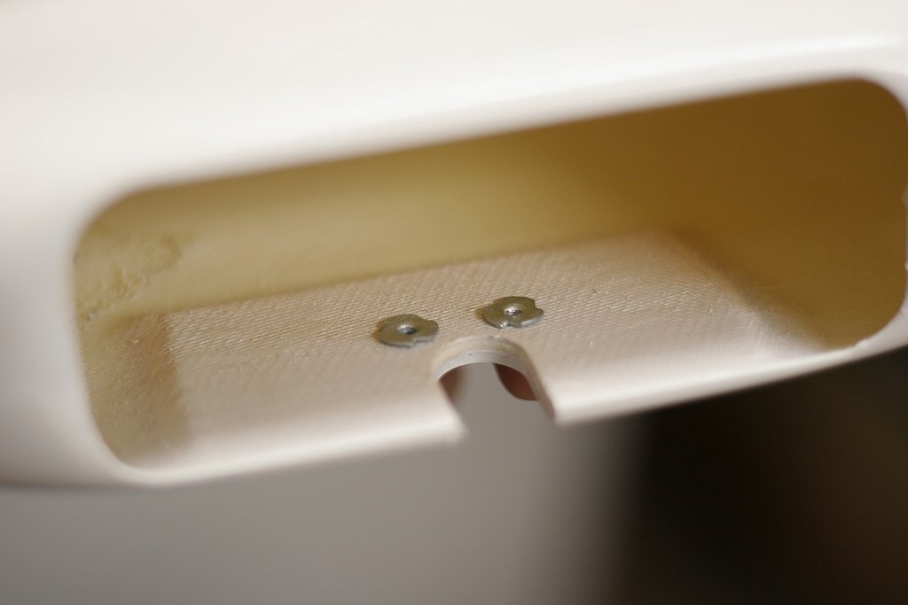
I was asked about the landing gear plate and I’d have to say it looks pretty stout. It’s a continuous piece of 1/4″ hardwood side to side… with two perpendicular pieces of 1/4″ hardwood glued to it. Those side pieces pick up alot of surface area and really shear the whole thing solid. The landing gear bolts go through the overlapping area which is 1/2″ thick, and again has its load spread out pretty far and wide.
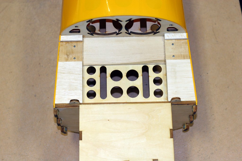
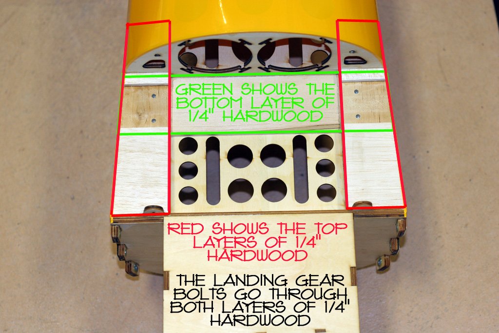
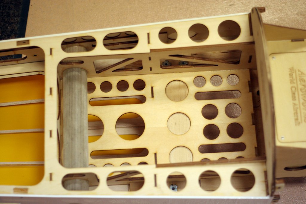
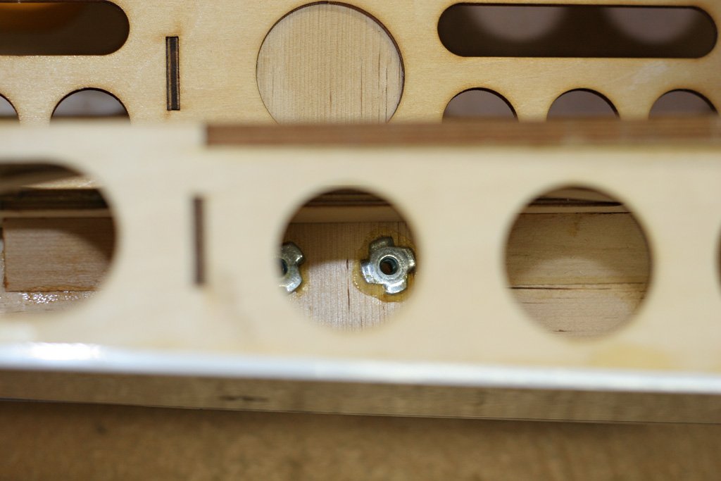
A shot from the top and also a shot showing the pre-installed and glued in blind nuts for the landing gear (again going through a double layer of 1/4″ hardwood that has alot of coverage or shear strength):
Still don’t have all the parts… hope to have everything by week’s end and start the assembly next week.
Meanwhile, as with the last QB™ I had, everything is real clean, real high quality. Also, one of these days I gotta ask Rocco if I learned this wheel pant mount from him, or him from me. Whichever, I’ve always thought it was the only way to go! And, here it is, already done:
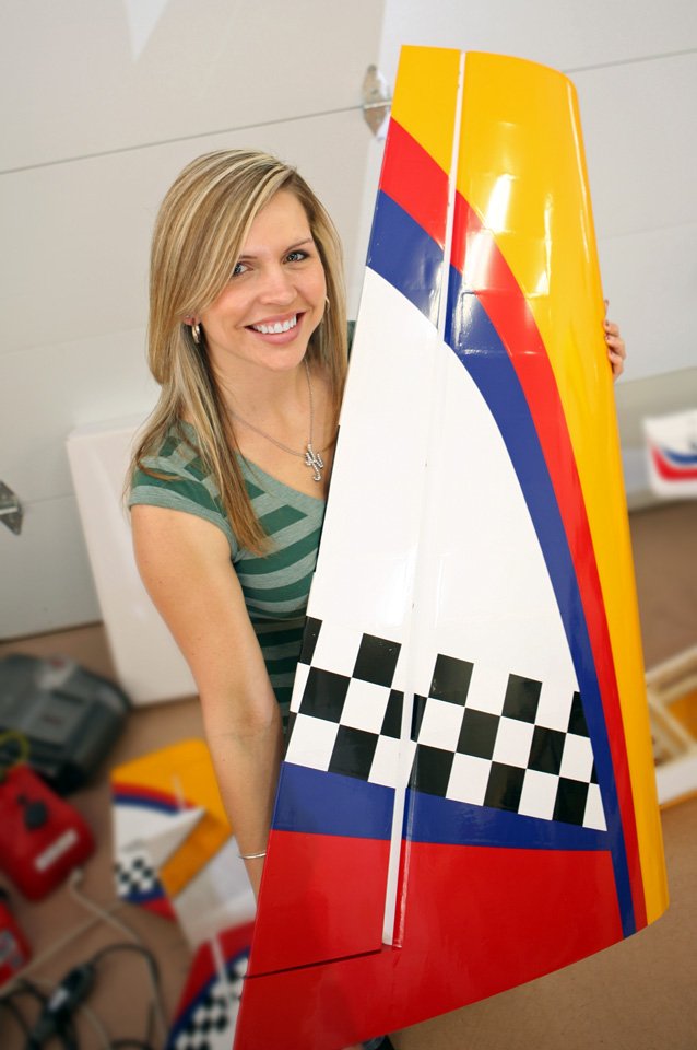
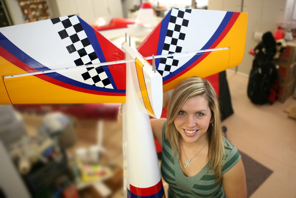
Still waiting on parts, so thought I’d snap some more pics. Here’s a couple of wing shots:
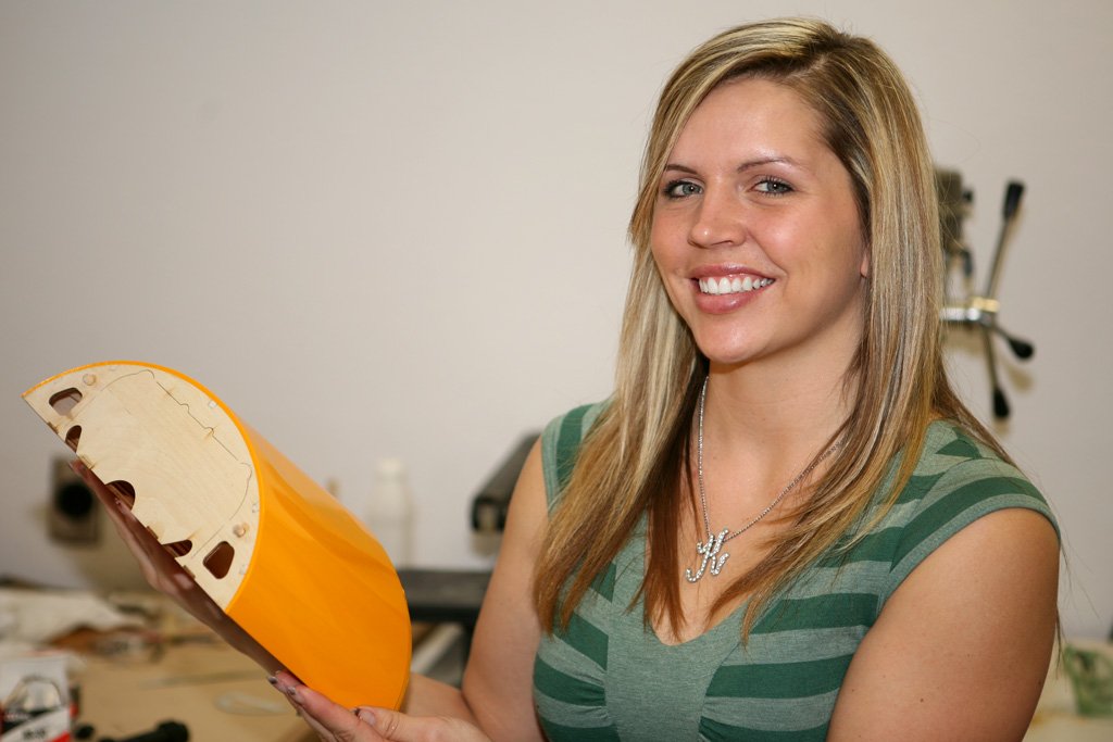
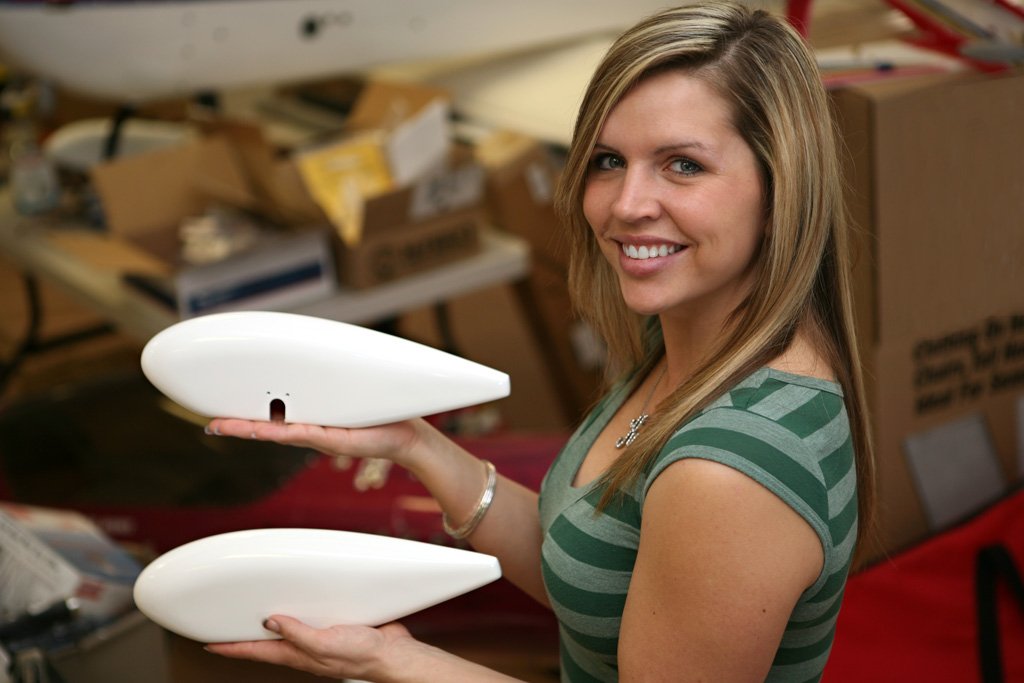
Here’s a pic of the the landing gear hatch, and another of the wheel pants:
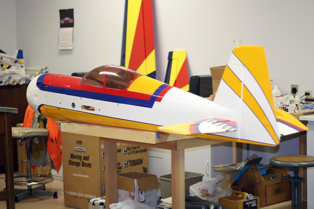
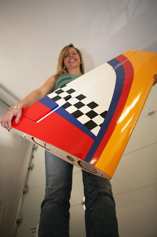
Here’s the plane, showing the cutouts for the rudder servos, receiver, batteries, tanks, et al… pre done:
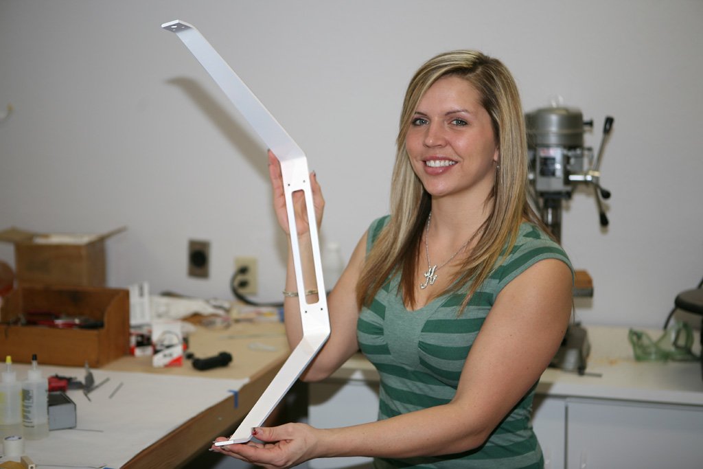
Here’s a shot of the landing gear:
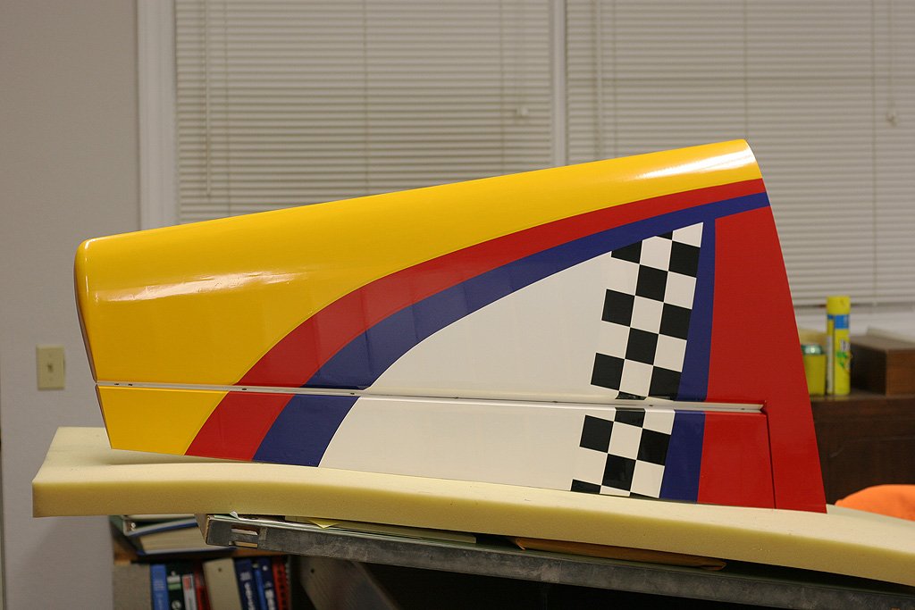
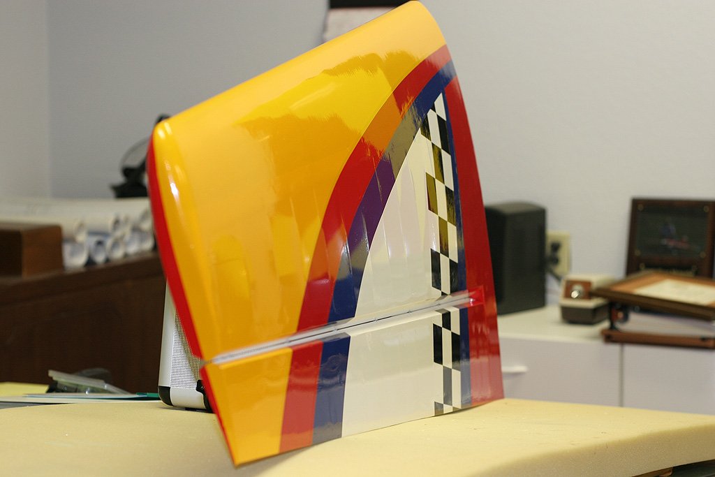
And also a shot of the rudder:
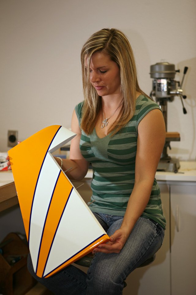
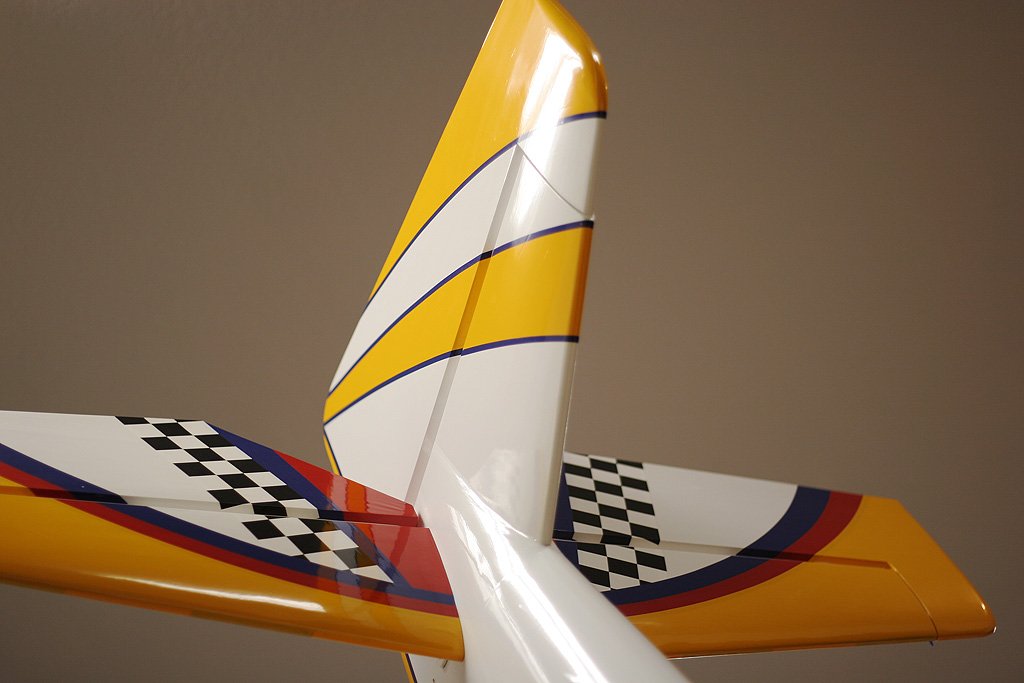
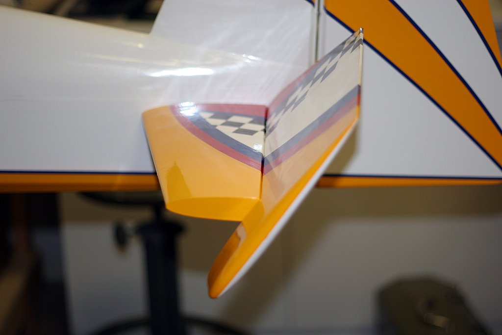
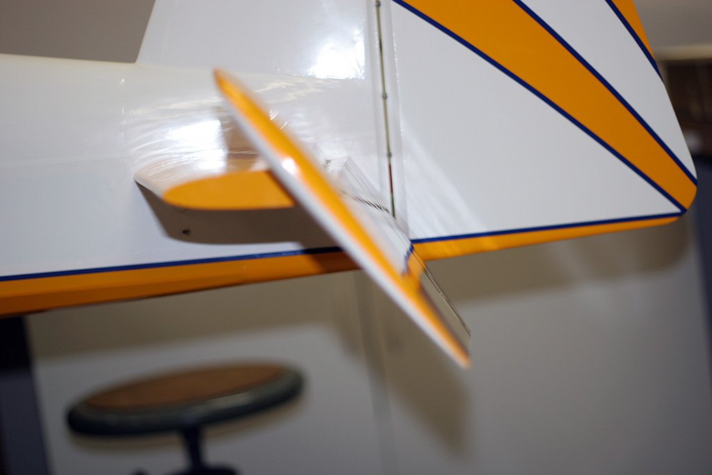
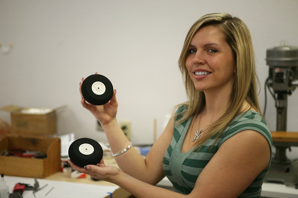
Here’s a shot of the lightweight foam tires, and also a shot of the tail section:
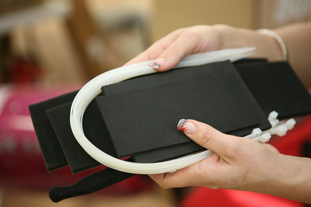
Battery/receiver/tanks foam; velcro straps, cable ties, et al (standard included items):
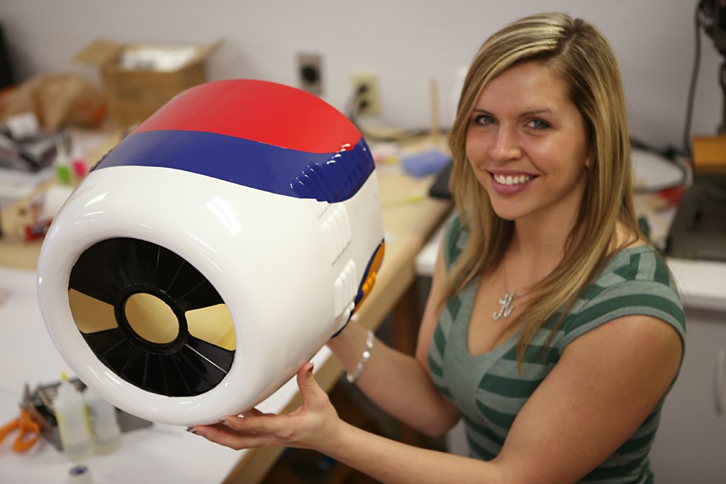
The cowl:
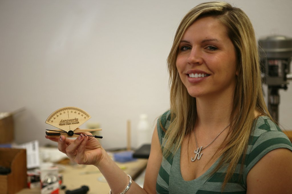
Here’s the included throw meter, nice touch:
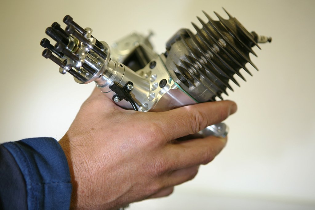
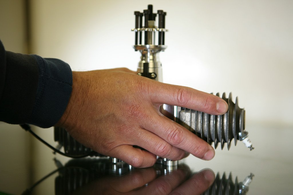
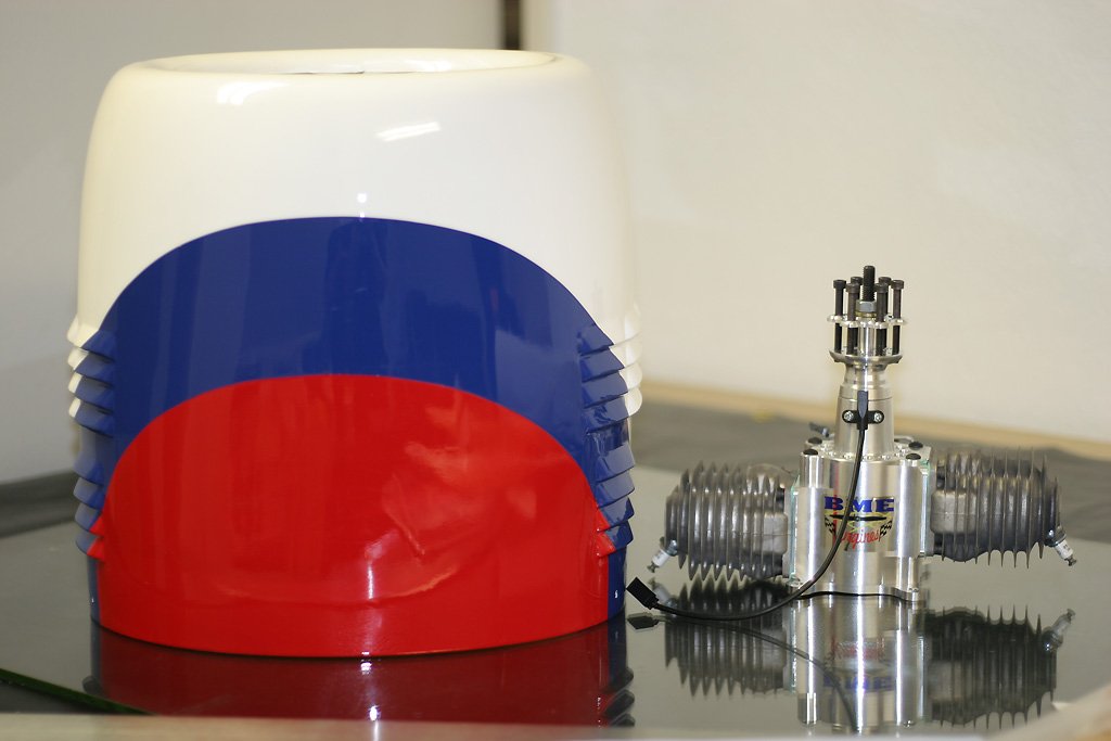
Going with a BME-115:
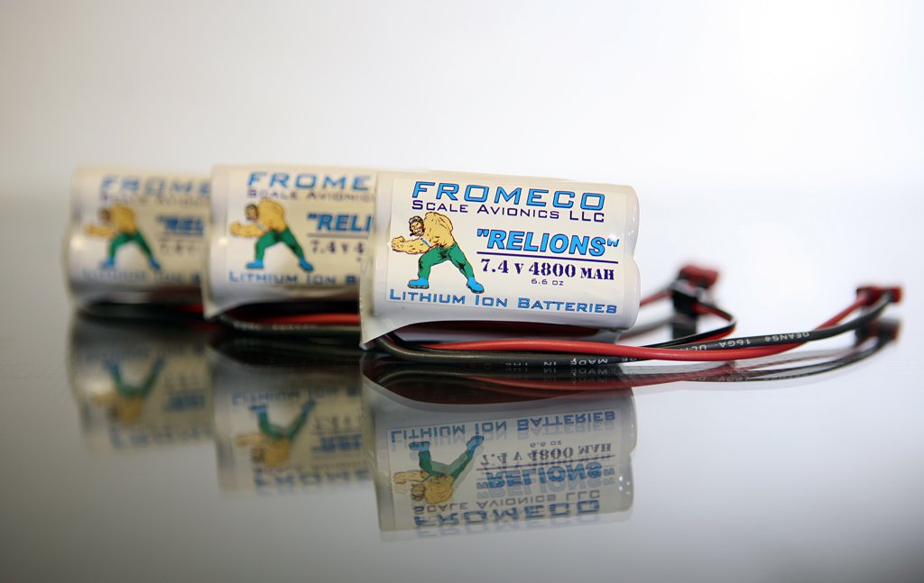
Here are the new style Fromeco 5200 ”Grunt” packs (with Relion 4800 labels):
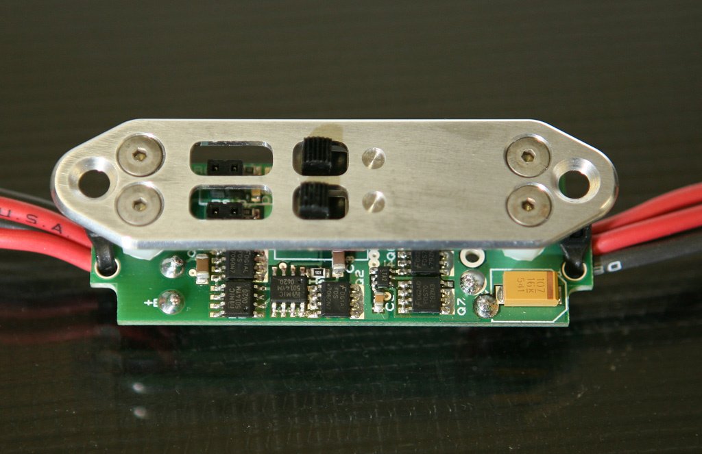
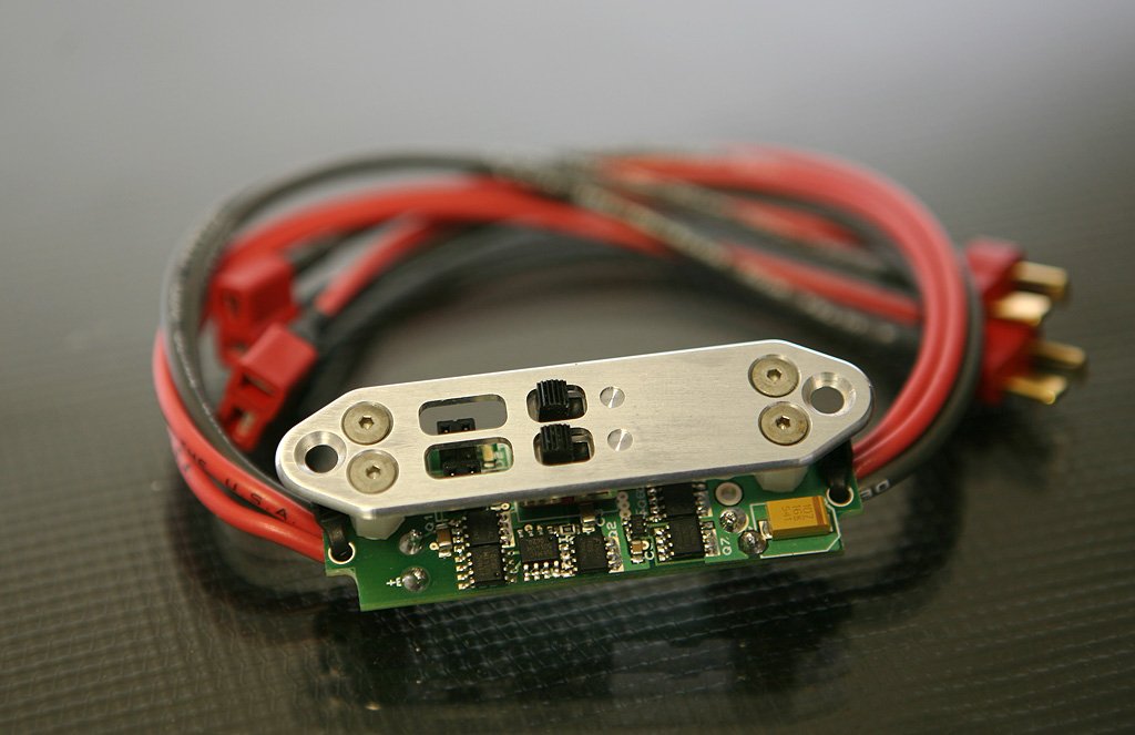
Here’s a new dual switch from Fromeco. 16 gage soft wire in and out, Dean’s Ultra’s in and out, dual charge/test jacks. Tried to let you see the circuit board… I think both switches are failsafe and also I think there is circuitry to keep both batteries draining instead of only one, even if the regs are not matched… I think. lol Let me get back to you on that:
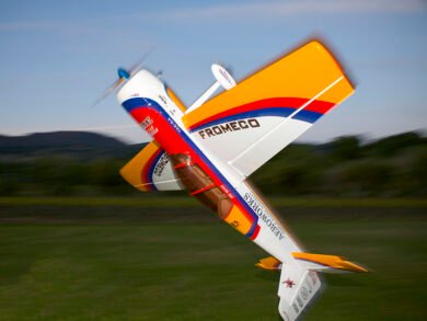
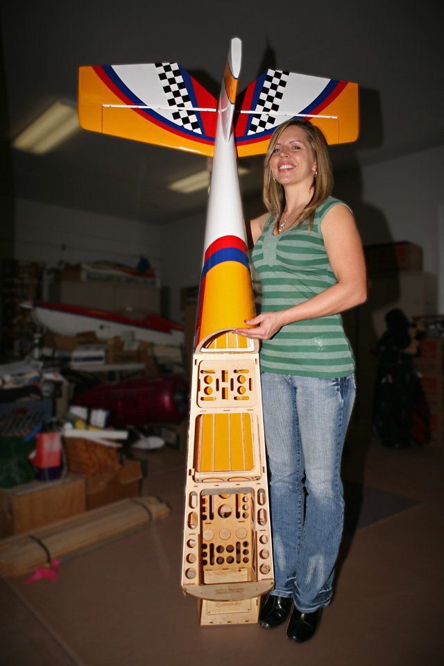
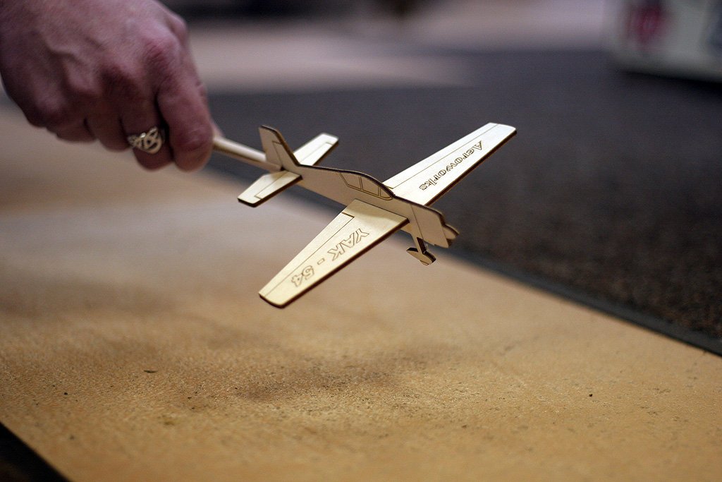
Here’s my AW QB™ coming in for a landing tonight. It’s one of the new stick planes from Aeroworks. It’s four pieces, that’s the kinda quick building I can handle. lol
The engine is really dwarfed by the cowl:
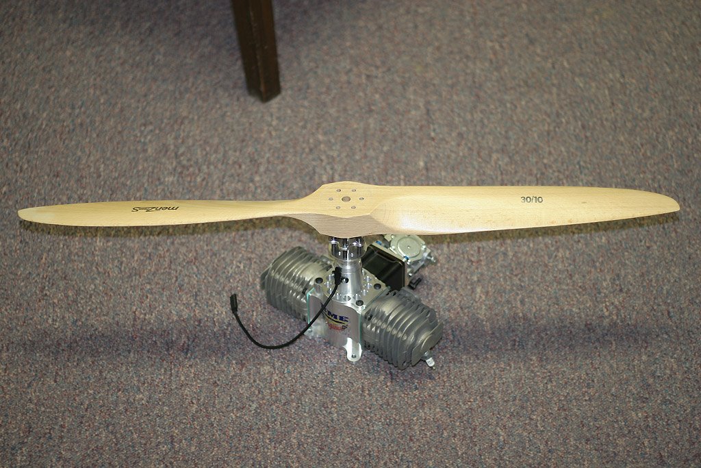
Charles Bradley says it will spin this prop, too. Ha, lol, hard to believe… but I guess this cute ‘lil motor is actually a beast in disguise:
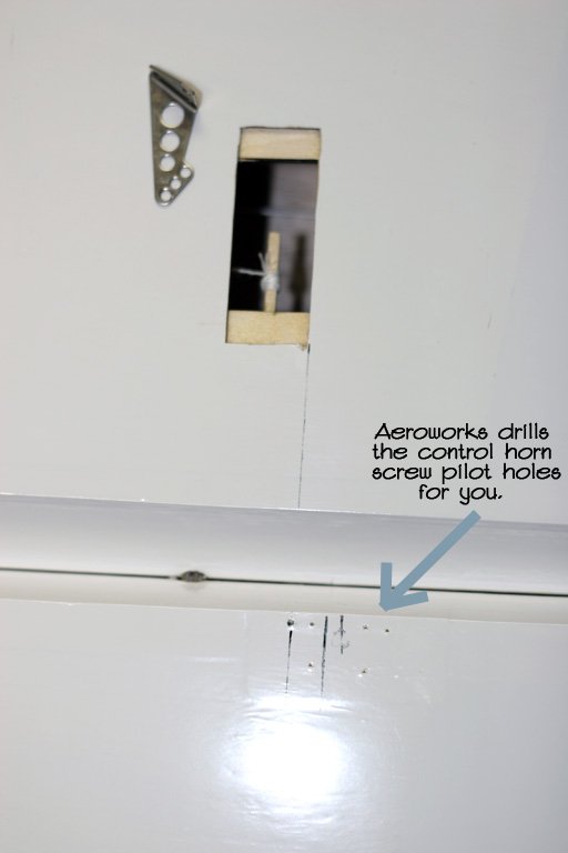
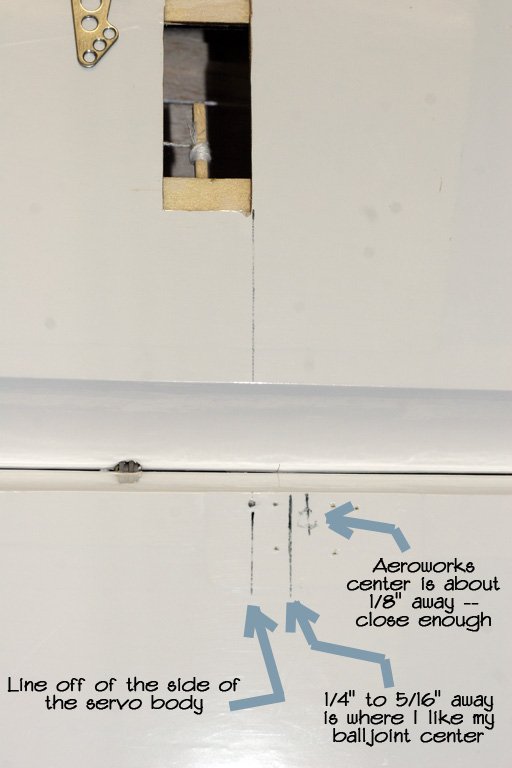
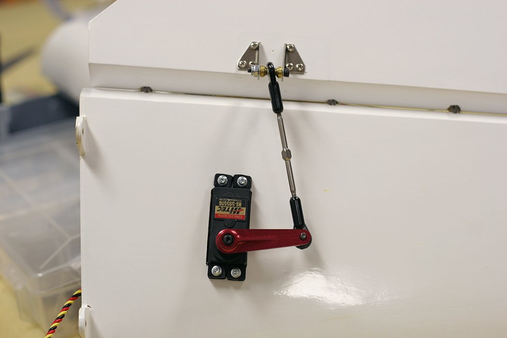
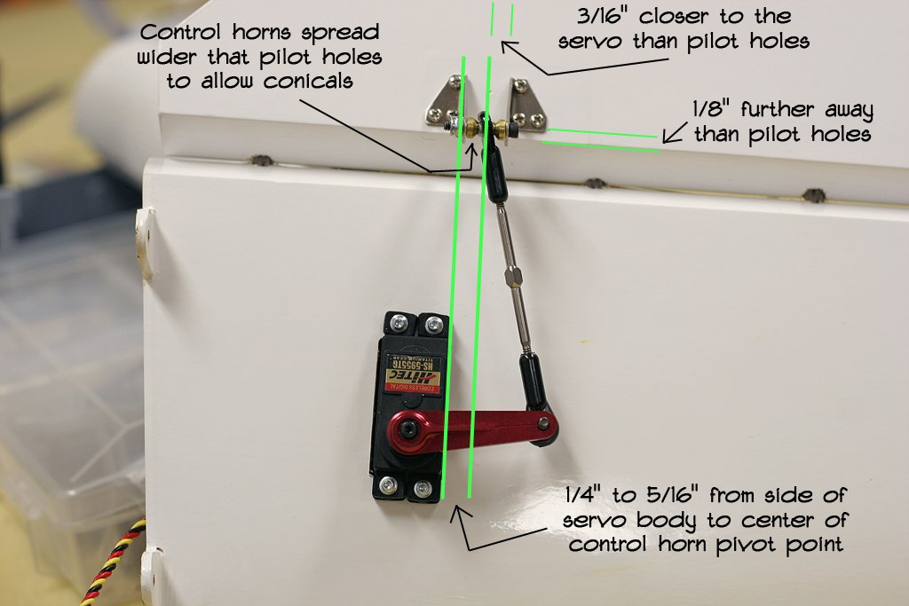
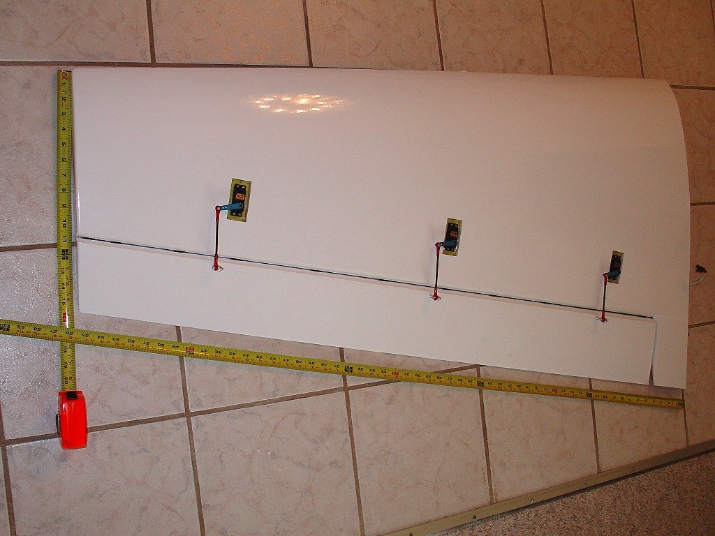
Got started on mounting the servos and control horns on the wings. When you go to mount the control horns you’ll notice that Aeroworks has already drilled pilot holes for you. You might wonder what the pen marks are… well only those who haven’t read any of my reviews before will wonder, lol… they show a line off the side of the servo body. From there I like to measure over 1/4″ to 5/16″ to center of my control horn ball joint. That gives me optimal torque throughout the throw range without imposing any undue leverage on the servo’s output shaft. If you use the pre drilled pilot holes you’ll only be an 1/8″ off my desired location. Good enough. On the 104″ Extra-260 QB™ I also pointed out that I would have the control horn edge an 1/8″ back from the bevel rather than right on it… for better linearity throughout the travel range. But, an 1/8″ is close enough meethinks:
Hitec 5955s on everything but the throttle (that will be a 5945):
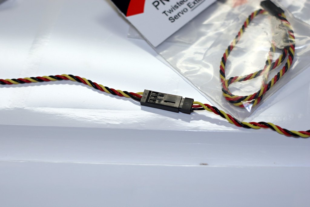
I like the new style Hitec heavy duty extensions the best, as well:
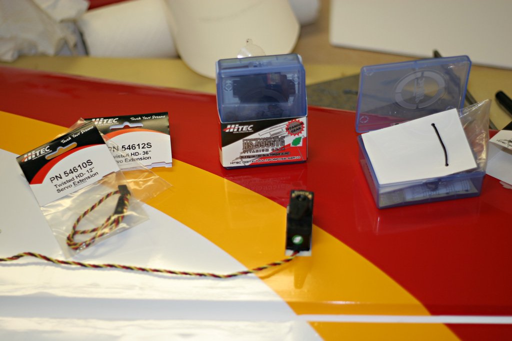
Not only do they have the right size wire (22 gage), twisted, but the twist doesn’t come undone. The connectors have a solid snap/click connection, too… different than any others I’ve used/seen. And, the quality is better than other brands I’ve used, where wires pop loose quite often, etc:
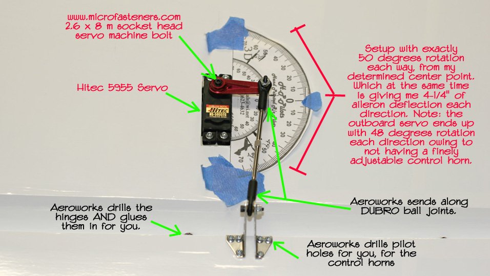
My friend Mark bolted down the servos and control horns for the ailerons. The aileron servo pockets already have a double layer of ply, just another step Aeroworks does for you. The control horns are pre drilled, so a caveman could put those in. DUBRO ball joints are included, and also steel pushrods with carbon fiber tube reinforcements. I used some titanium pushrods only because I had them already. On my last QB™ I used the stock pushrods and they worked just fine.
I figured this QB™ Yak would be similar to my QB™ Extra and it was… same 50 degrees each way off a “determined” center point, yielding the same 4-1/4″ deflection each direction off neutral. As with the last QB™ the control horns cannot be fine tuned quite enough for perfect synchronization, but close enough, with the outboard servo arm moving 48 degrees each direction for the 4-1/4″ deflection on the aileron. Not millwright perfect, but close enough for government work.
Without using rocketcity style horns or putting things precisely where I would, Aeroworks still manages to get everything extremely close to perfect. Plenty good enough. Still wonder if though the years Aeroworks got all these ideas from me, or me from them. lol:
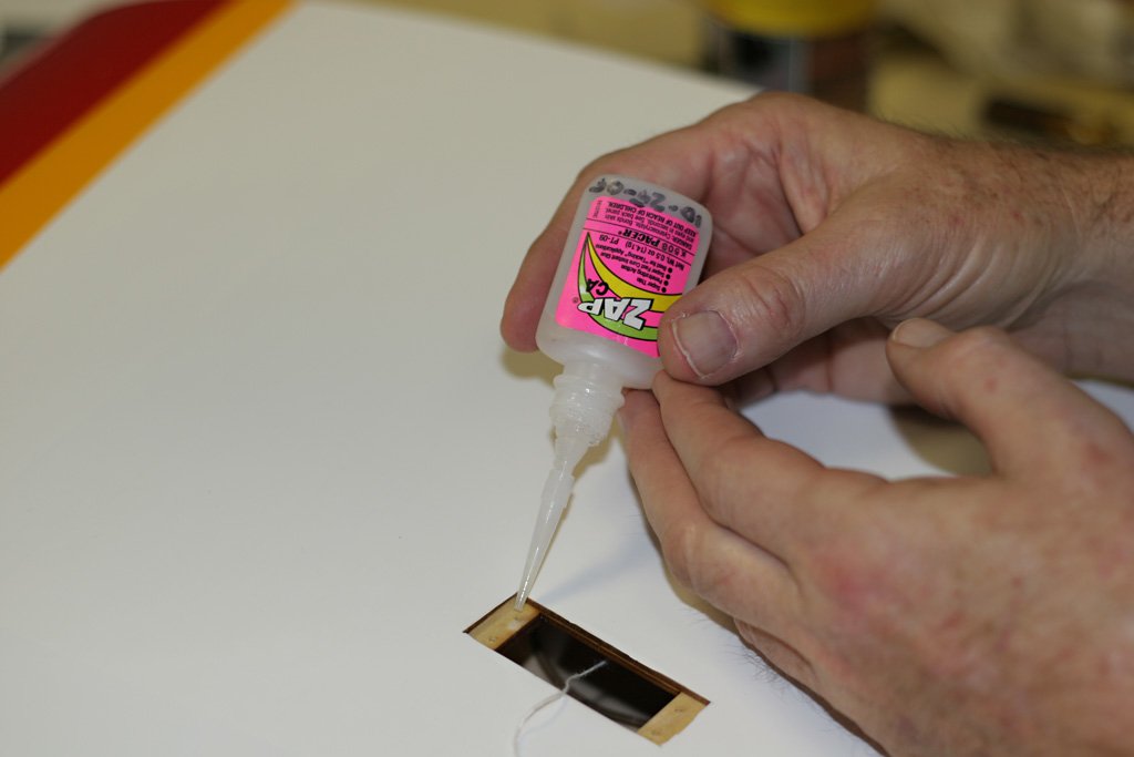
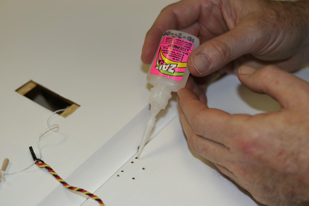
Mark’s busy on the second wing now… he used ZAP thin CA glue in all the wood screw holes (for control horns and servo mounts). This strengthens the wood up quite a bit. Again, under the servo pockets here, is another layer of ply that I usually have to cut and glue in, but Aeroworks has taken care of that already… along with so many other steps that I usually have to take to assemble an ARF. But, this ain’t just an ARF, it’s a “QB” :
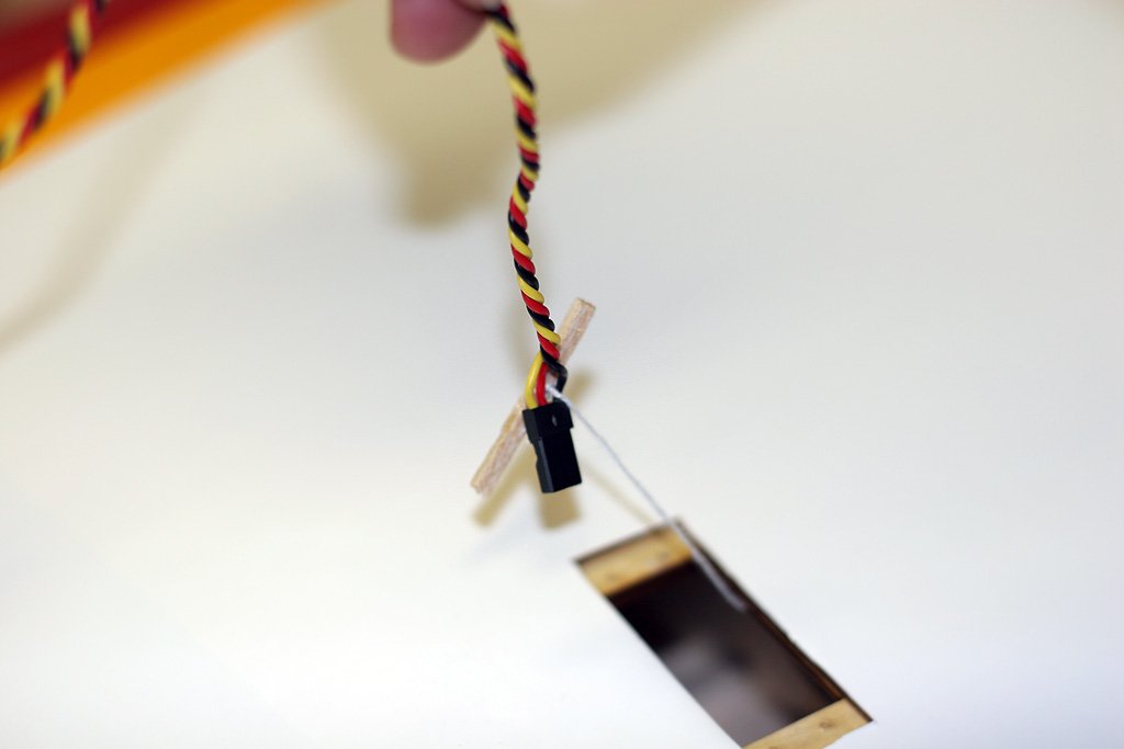
Aeroworks leaves strings in the wings for pulling the aileron servo extensions through. Mark was showing me his method for using them… fine for this plane as there is no drag and lots of room in there… but I wouldn’t do it on a wing with less room inside. ‘Course, come to think of it, I’ll probably cut those connectors off in favor of Dean’s 1003s anyway… so it really doesn’t matter how much abuse they take:
Aeroworks doubles up on the outside hinges on the ailerons… this is good practice, imo:
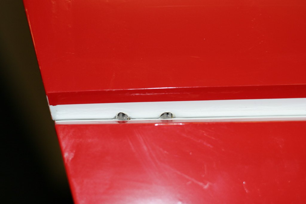
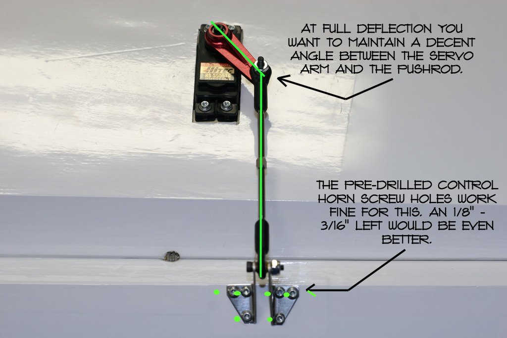
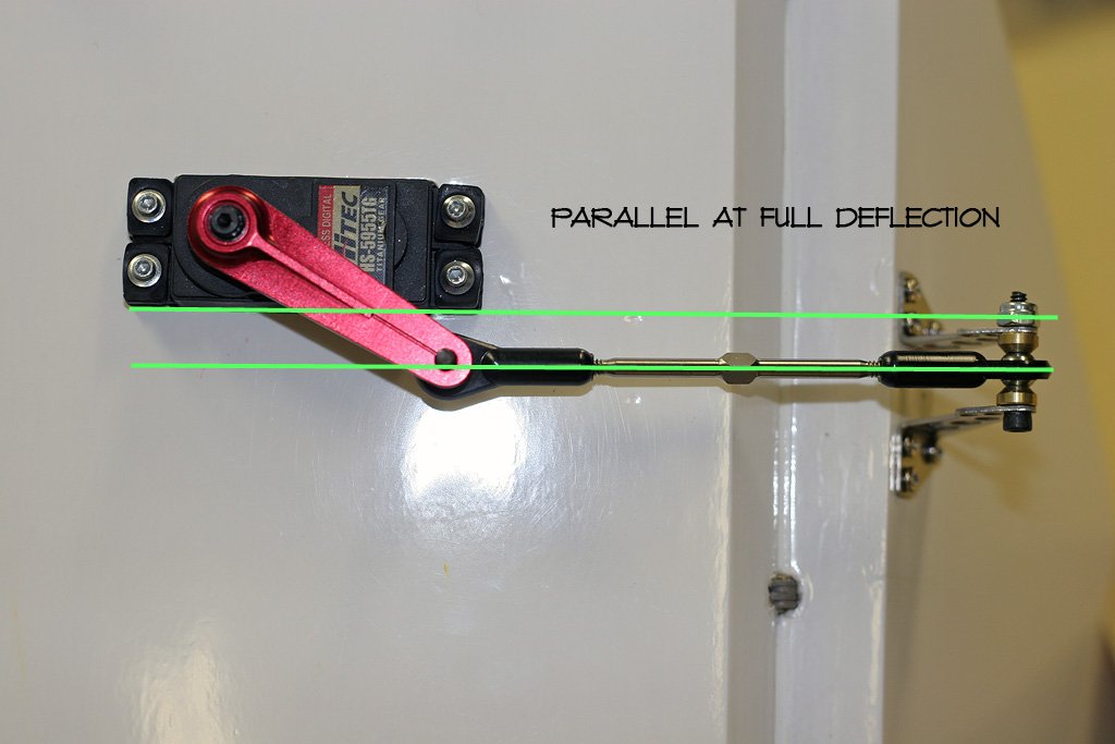
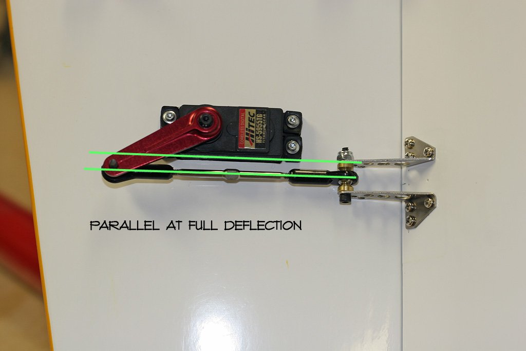
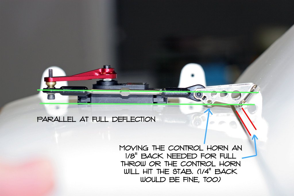
Couple things I’m always looking to achieve with the geometry… 1) is the control horn in the right place to keep some angle between the servo arm and the pushrod at full deflection (this avoids leverage against the output gear that leads to case damage, loss of torque, failures, etc; and also situations where one servo goes past parallel and gets stuck there when a ganged servo moves back to center. I’ve seen these types of failures, and also the people that set them up blaming the manufacturers.) And, 2) the pushrod being parallel with the wing surface at full deflection (avoiding prying leverage against the output gear which also leads to case damage, loss of torque, failures, blaming the manufacturer, etc.):
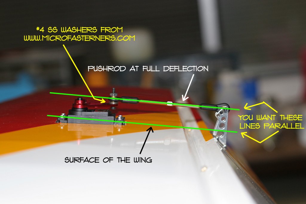
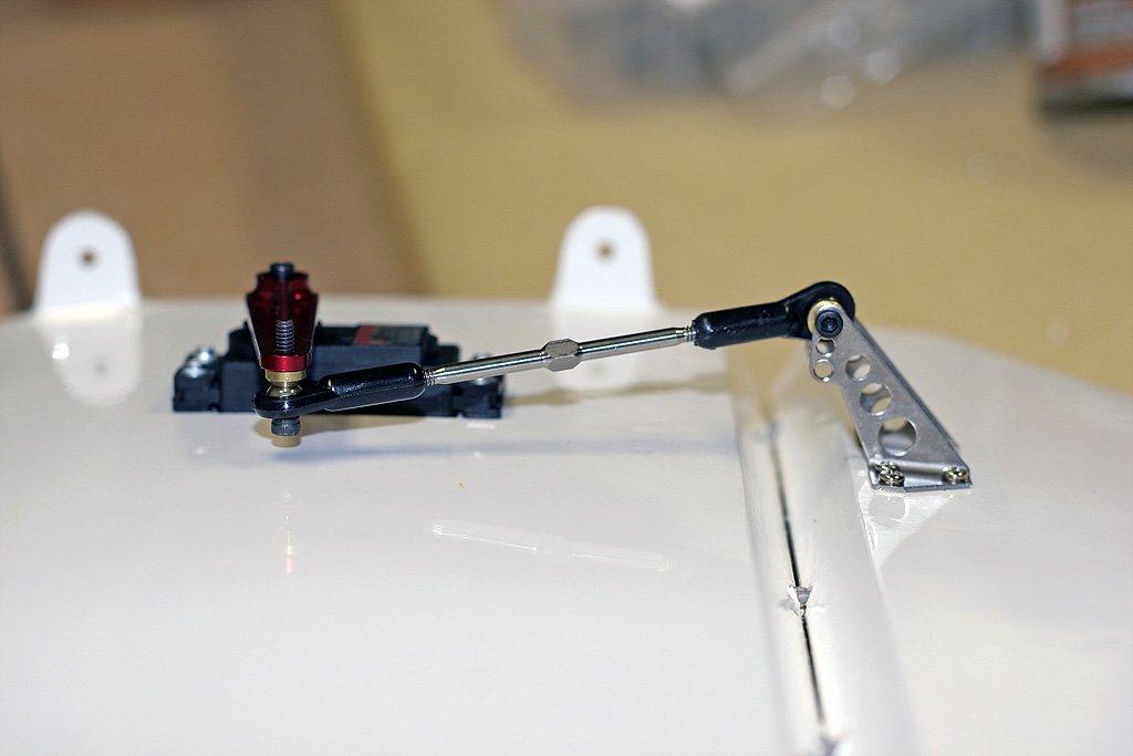
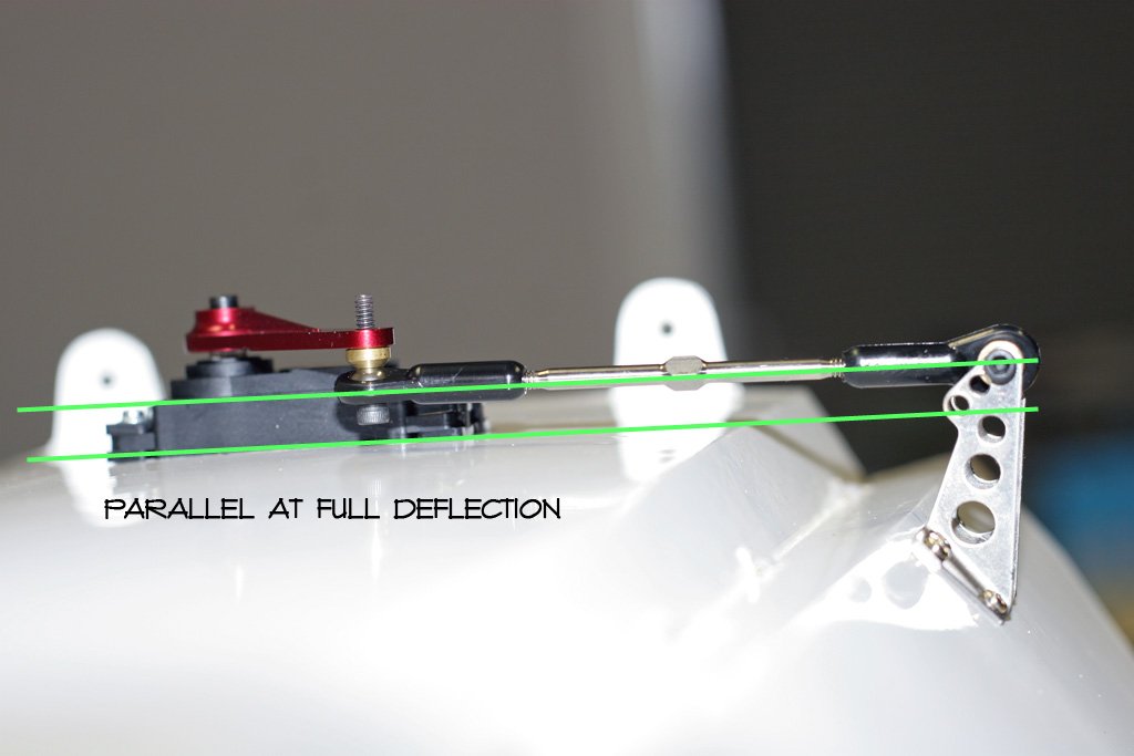
Once you establish your control horn height to get between 50-55 degrees each direction off center to achieve the max travel you, personally, will need… then getting the pushrod to be parallel to the wing surface at full deflection becomes a matter of how high to have the pushrod on the servo side. The means for adjusting that height is with which servo arm brand you use and whether or not you put the pushrod/balljoint on top or underneath the servo arm. In the picture below I have the pushrod underneath the servo arm to get the geometry I’m looking for. Additionally, I’ll use spacers… the included conical (comes with balljoints), one washer, two washers, whatever… to get the height I want and also be free of binding (balljoint to servo arm) throughout the range of travel:
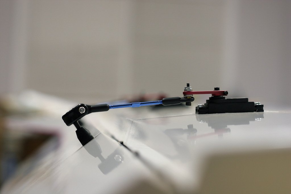
Again, I’ve never talked to Rocco @ Aeroworks about plane setup, ever. But, he seems to understand all these considerations. I keep wondering who learned this stuff first, me or Rocco? lol Example, from the 100cc CD manual… Rocco/Aeroworks shows the pushrod/balljoint underneath the servo arm. Which might look funny to some people at center, but it looks right at full deflection, which is when you really need it. Good job, Aeroworks! Also, Aeroworks is showing heavy duty Hitec plastic servo arms. I’ve seen some GS guys run them lately. Apparently they can take it. I wanted to try them on this plane… but I just can’t get my mind around it. lol:
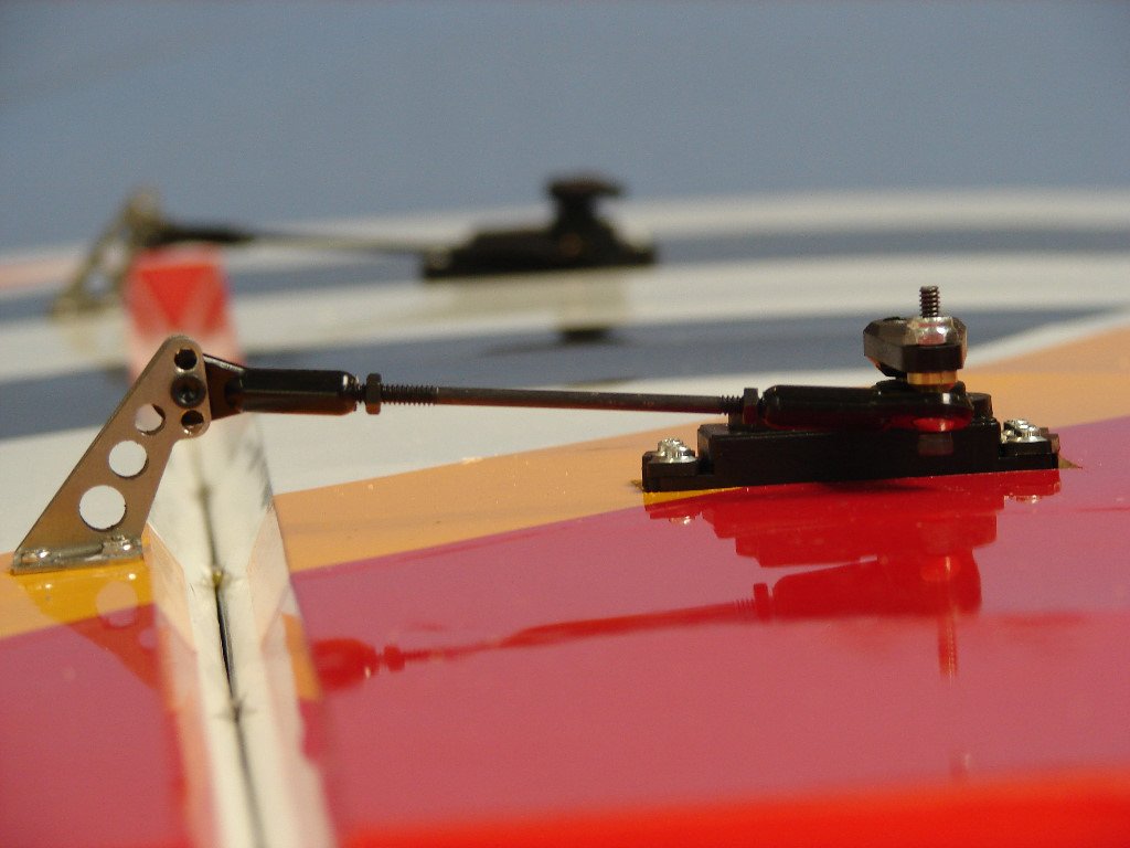
Back to geometry consideration #1. If you don’t have a decent angle at full deflection you will be prying on the servo output gear (case failure, gear failure, plane failure, etc.):
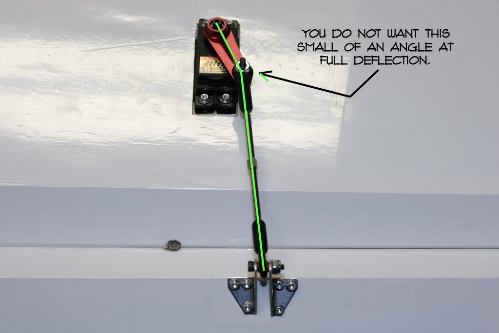
Also, without a decent angle at full deflection one servo can go past parallel and a ganged servo can hold it there. I’ve seen this happen… not pretty. The guy was blaming the servo manufacturer, btw:
I worked a bit on the elevator hinges. The aileron hinges were fine, I got all the throw I wanted without any binding, they were real free. But, on the elevators I want pinned bevel to bevel throw. There was a little epoxy here and there making it drag just a tad at full throw. I put a new xacto blade in and carefully cleaned up the elevator hinges:
You’re looking for the “sweet point” compromise between resolution (more servo arm travel) and servo geometry leverage (maintaining a decent angle between the servo arm and pushrod). You want side load, not pry load. Hey! That’s a good one! lol
55 degrees is pretty much max optimal. Anywhere between 50-55 gets me the resolution but geometry I need. Less than 50 I can start to feel resolution drop off, more than 55 and I lose the geometry I want.
As a side point, most planes I see are not getting even 50 degrees and have low resolution. Especially throttles that I see with like 15 degrees one way and 30 degrees the other. And, most all pull/pull rudder setups. On a 40% I use a 4″ bellcrank/servo arm and a 5″ control horn… I often see it the other way around which yields like 25 degrees servo arm travel each direction. No resolution a’tal.
99.9% of the tailwheels I see have totally messed up geometry, too… but that’s another subject. lol
Most GS planes I see would indicate that most GSers don’t think much about this kinda stuff a’tal. There surfaces and throttle are setup like on/off switches and they wonder why they look so herky/jerky. Kyle Woyshnis can fly all that stuff and make it look smooth… I’m too old, I need to get me some resolution.
While we’re on the subject. I worked out an elevator today/yesterday. I shot for 60 degrees each way (120 degrees total), but would have to have a slightly taller control horn or slightly shorter servo arm to get it. I got 58/58 and it came out correctly… but I could get 60/60 if I either drilled the servo arm or went rocketcity style on the control horn. Again, I’m happy to get 50-55/50-55, you have to be very precise to get 60/60. Here it is:
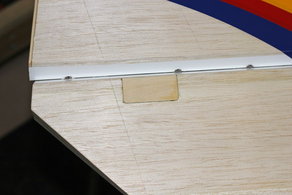
Here’s some notes on how I drilled my own pilot holes located differently than the factory pilot holes… and how I measure to come up with that location:
The combination of not being 90 and also being out of level has alot of people looking at it weird and also telling you it’s wrong. lol:
But here are four reasons why it is not:
It doesn’t take but a minute to drill pilot holes in new locations. And, Aeroworks gives you a generously sized hard point to keep this from being any kind of problem. I’ve seen, and replaced, some slack factory hard points in these 1/3 scale ARFs from other manufacturers, but never from Aeroworks, their hard points are solid:
I’ve been questioned about servo arm and control horn offset… some old timers think it needs to be at a true 90° for the plane to be axial, and require no differential. But, actually I couldn’t be more linear and therefore couldn’t be more axial with all the surfaces including the ailerons. The magic on this (and why I prefer some offset) is a little thing called a protractor. Not only will it get you linear, hence perfectly axial, but it will get multiple servos on a single surface perfectly matched. Example, any 40% I’ve built with six aileron servos… each of those six servos will travel 55 degrees in each direction from neutral to achieve the exact same amount of aileron surface travel (let’s call that 4″). At full deflection right aileron up all three right aileron servos will have traveled exactly 55 degrees from neutral… and at the same time all three left aileron servos will have traveled exactly 55 degrees down to an equal 4″ aileron surface movement. Perfect linearity, perfect synchronization of servos, and perfectly axial. It’s not a trivial thing to me, I wouldn’t have a plane any other way. Once you understand it, and accomplish it, there just is no other way. I’ve learned after doing this on many planes that I prefer some offset, actually. Oftentimes, due to the geometry setup I use, it makes it easier to get perfectly linear… 55/55 each way from neutral, all servos. It’s a beautiful thing, at half stick, one aileron is up exactly 2″ and the other is down exactly 2″ and they’re both as quiet as mice. At any transmitter stick position you have perfectly synchronized servos, having moved the control surface the exact same amount… with ailerons that includes the one side’s movement up versus the other side’s movement down. Total perfection.
I do not measure my control horn heights from the hinge line on multiple servo surfaces. That’s not exact enough, I use the protractor to adjust the control horn heights until all servo arms travel the same number of degrees to get the control surface to move the same distance. (e.g., all 3 servo arms on one aileron move exactly 55 degrees up and down off neutral, to have the aileron move exactly 4″ up and down off neutral — if you disconnected any two aileron servos, the remaining one would still have its servo arm moving exactly 55 degrees in each direction off neutral to have the aileron surface move 4″ in direction off neutral — that is ideal, and that is how I setup all my planes).
With the QBs I make a slight exception and the travel is just slightly different one aileron servo to the next (50/50 on one, and 48/48 on the other — both achieving 4-1/4″ of travel to the aileron control surface from neutral), which I accept as, well?, acceptable. lol
Again, once I started using the protractor to set things up absolutely perfectly, I noticed I preferred some offset. Not alot of offset like 3W sets up with their 3W control horns, but some offset, from 1/8″ to 3/8″ works for me. Below is a pic of the stock 3W setup ailerons with approx 3/4″ to 1″ off offset. I could not make those 3W horns work acceptably, I replaced them:
This is the problem that I see on pretty much every plane I’ve ever run across. My solution for this evolved over a couple of months after getting my first Hitec programmer. Once I realized I could program the servo any way I wanted… I started thinking, why not then, get the geometry/linearity/resolution perfect first? Only after I had accomplished this did I realize that programmer or no… this setup should be done on all planes with all servos. If not field programmable then unihubs should be used and custom drilled Nelson servo arms mounted to the unihubs. So that all servos would have a zero sub-trim. The problem then is finding servos that are perfectly linear out of the box ( in my testing a few years ago Futuba’s were, JRs not even close). Again, the protractor lined up with the servo arm is the magic for getting this stuff perfect.
And, yes, I’m talking about the offset of the neutral position of the servo arm. I do not worry about it being a true 90 to the servo body. Same way that I do not make the pushrod parallel to the servo body at neutral. Tedious, yes, because I have to keep adjusting the length of the pushrod until that protractor indicates I’m 55 degrees each direction off the “determined” neutral to be exactly 4″ up and down on the control surface. I then have to do this with all three, or however many, servos. Again, though, once you get it once… you won’t do it any other way from then on.
One final point on this comes up when people tell you that the pivot point of the control horn should be in the hinge line. Well, that is another reason I do things the way I do. You see to get in the hinge line you have to have a control horn that has alot of offset from it’s bolt down location, due to the bevel. Well, on 40% that bevel gets pretty big and you are looking at a big offset to get to the hinge line. I don’t like a single bolt style control horn sticking that far out, looks like trouble to me. I accept the 3/8″ offset from a rocketcity style and no more. This makes control horn pivot point to hinge line center offset a given for me. Now, the style horns Aeroworks is using here, they are stout even offset way out there. But, the problem with them is that they do not have a find adjustment for height, only a course adjustment. So, unless I have that style custom made for each of my planes, I’m going to have offset. Aeroworks, building this plane from scratch, was able to work out good geometry with this horns, that’s why I used them. Now, if Aeroworks had the outboard servo just a couple inches closer to the root they’d be perfect, 50/50, 50/50 on the two aileron servos. But, it’s almost perfect, and plenty close enough.
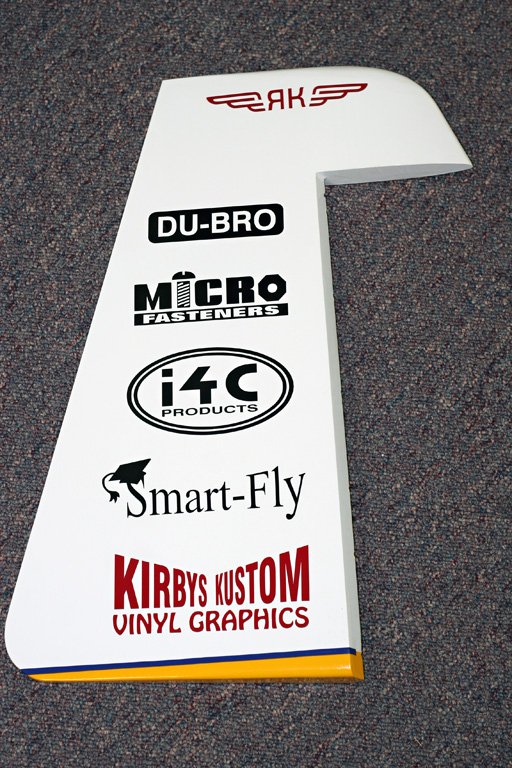
On to my favorite part of the assembly! The box from www.kirbysgraphics.com showed up today! Woohoo!
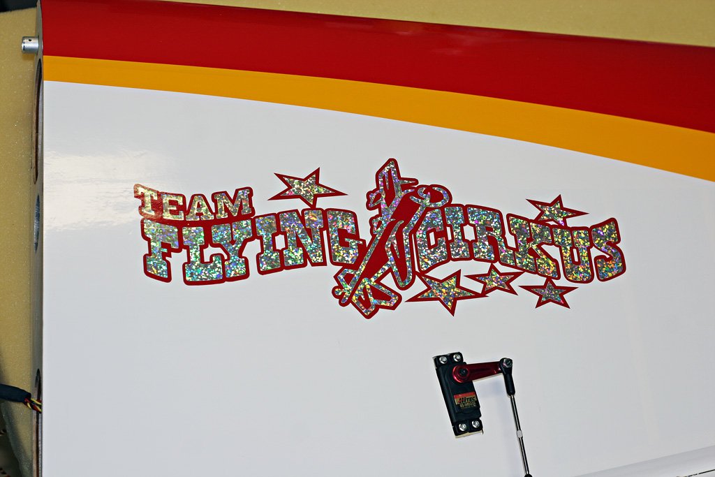
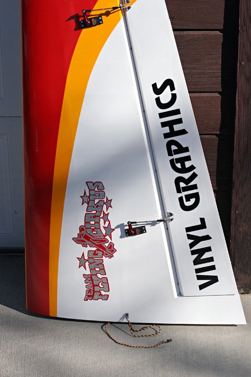

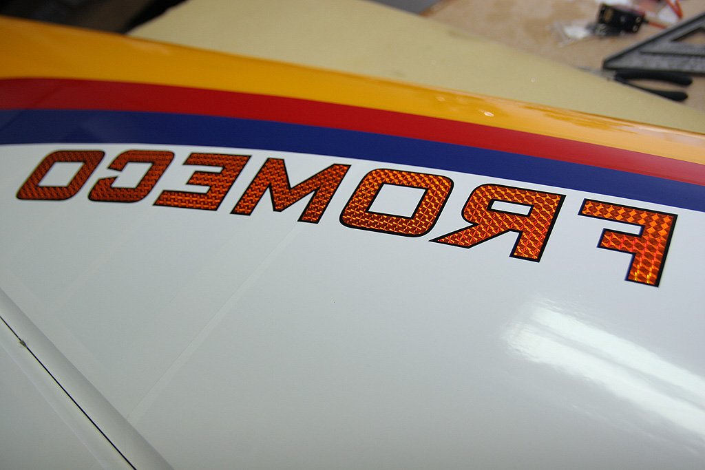
I was about to put on the BME graphics so I went to iron down the covering on the hatch… guess what?… that ain’t cover’n, that’s paint! Like the best custom builders do… sweet:
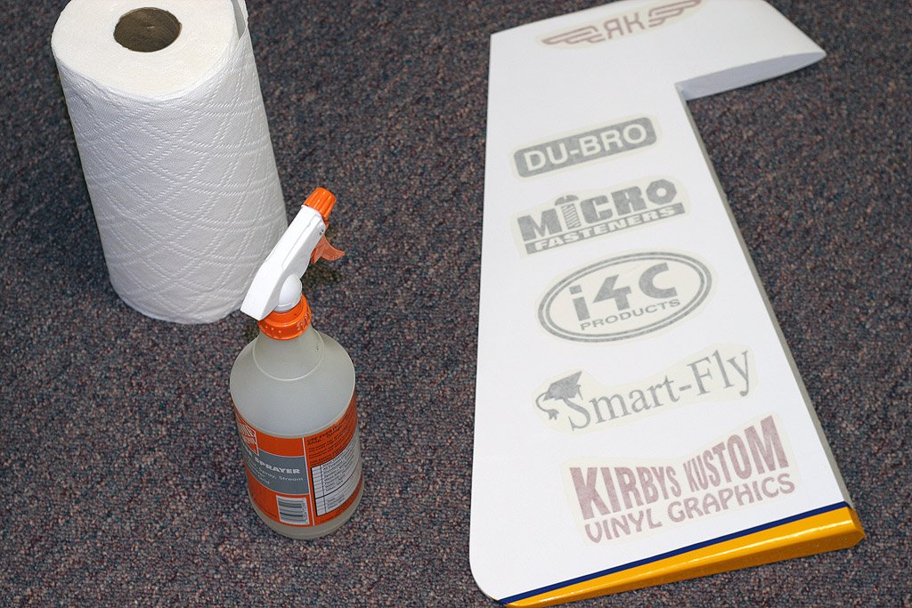
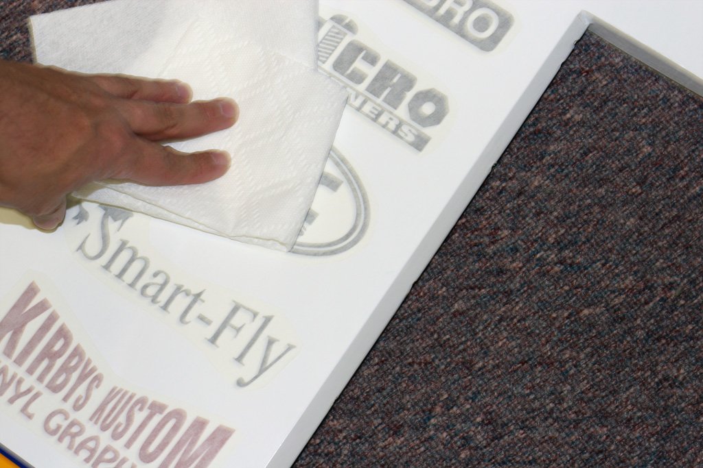
I’ve never talked about applying graphics. I do like the Kirby’s instructions say… to use like Windex to soften up the backing before you remove it. But, what I’ve come to like using is denatured alcohol… and also to spray it on lightly and avoid spraying it around the edges. After that I immediately wipe it off/down with a paper towel. This prevents it from over soften’n the backing and also from having it leak under the backing and get under the vinyl. I’ve put down alot of graphics, lol, and this works pretty fast and easy for me:
Had to do some real work for a few days, but now I’m back on this thing. Me and Mark programmed one wing and as I always say, it’s just so satisfying… the servos are perfectly synchronized throughout the entire range of travel. Yes! (no picture, sorry)
Also, I saw Gus Stutsman had Aeroworks wing bags for his 94″ YAK, so I decided to try the Aeroworks wingbags out this time for my 104″ YAK. They look great! Got the Aeroworks stab bags, too!

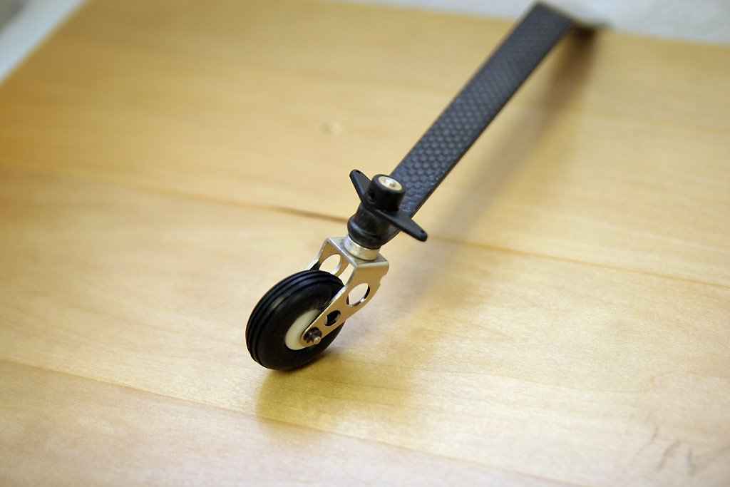
Upgraded the stock tailwheel to the lighter/stronger Aeroworks CF tailwheel: